
Think of wiring diagrams as the roadmap of your mobile home’s electrical system. Knowing how to read and use them is crucial, especially for mobile homes with limited space, and you need to get things right first. This guide’s got you covered, whether you’re troubleshooting a pesky issue, planning some DIY upgrades, or just wanting to understand the maze of wires behind your walls. We’ll break down types of diagrams, decode symbols, and even guide you through creating your own. So buckle up, and let’s electrify your knowledge!
What is a Wiring Diagram?
Let’s talk about the star of the show: the wiring diagram. Picture this: you’re looking at a map before going on a road trip. You see highways, rest stops, and some cool spots. A wiring diagram is basically the Google Map of your mobile home’s electrical system.
But what exactly is a wiring diagram? In simple terms, it visually represents how your home’s electrical wires and components connect and interact. You’ll see lines, symbols, and numbers working together to show you the big electrical picture.
Now, why should you care? These diagrams are lifesavers in understanding how electricity flows through your home—planning on adding a new light fixture? Check the diagram. Troubleshooting a circuit issue? The diagram is your go-to guide. Trust me, it’ll make your life a whole lot easier.
But wait, there’s more. You’ll often hear terms like ‘circuit diagrams’ and ‘electrical schematics’ thrown around. While they might sound like a different beast, they’re just specialized wiring diagrams. Circuit diagrams focus on the path of electrical flow, while schematics dive into the nitty-gritty details of each component.
Why Mobile Home Wiring is Unique
Mobile homes come with their own quirks and nuances that make their electrical systems different from traditional, stick-built homes.
First up, let’s talk space—or lack thereof. Mobile homes are, well, mobile. This means everything needs to be compact and efficient. There’s no sprawling basement or attic to hide miles of extra wiring. Your electrical system has to be a master of optimization. It’s like packing a suitcase for a week-long trip in a carry-on; every inch counts!
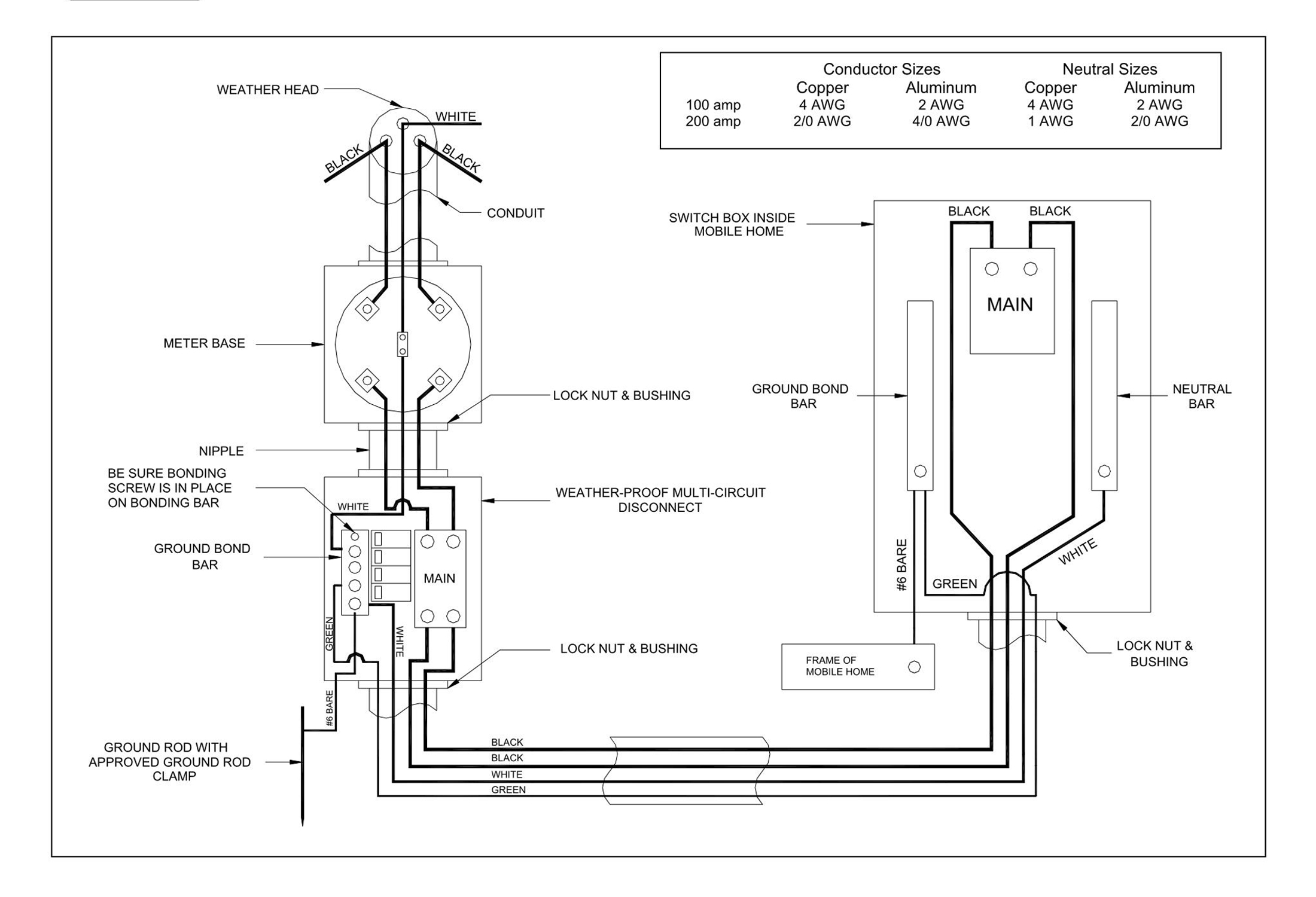
Next, building codes. Oh yeah, these are super important! Mobile homes follow specific federal guidelines, not just local codes. These might include things like special circuit requirements or even specific types of wiring materials to withstand the rigors of moving. Yep, your mobile home’s wiring needs to be roadworthy!
Last but not least, let’s chat about electrical loads. Appliances in mobile homes often require less power to operate efficiently. That makes sense, right? Less space generally means smaller appliances, which translates into different electrical needs. This impacts how your wiring and circuits are set up, making understanding your specific wiring diagram even more crucial.
Types of Wiring Diagrams
Each wiring diagram has its own perks and best-use scenarios. Whether you’re a DIY newbie or a seasoned pro, understanding these types will make navigating your mobile home’s electrical landscape a breeze. So, let’s crank up the volume and dive into the kinds of wiring diagrams you might stumble upon.
1. Schematic Diagrams
Think of these as the ‘big picture’ diagrams. They give you a broad overview of how the electrical components relate, like how a world map shows you continents and oceans but not every city. It is super helpful for understanding the core structure of your electrical system.
2. Wiring Harness Diagrams
Ever heard of a wiring harness? It’s a bundle of wires protected by an outer layer. In a mobile home, these are often used to save space and keep things tidy. Wiring harness diagrams focus on these bundles, showing you where they go and what they connect to. It’s like your home’s electrical cheat sheet!
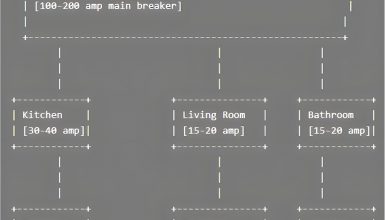
3. Block Diagrams
These guys simplify complex systems into, you guessed it, blocks. Block diagrams are your new best friend if you’re not into the nitty-gritty and just want a high-level view. They’re like the CliffsNotes of wiring diagrams—short, sweet, and to the point.
4. Wiring Layout Diagrams
Alright, fasten your seatbelt for this one. Wiring layout diagrams are the real-deal, detailed roadmaps of your electrical system. They show you where each wire goes, the type, and even the color! This is your go-to guide for planning a DIY project or a major rewire.
Reading a Wiring Diagram
Reading a wiring diagram is all about recognizing patterns and connections. Don’t sweat it; deciphering ancient hieroglyphs is not as tough. A few basics, and you’ll be reading them like Sunday morning comics.
A. Symbols and Their Meanings
First up, let’s talk symbols. No, not emojis. Electrical symbols! These are the tiny drawings you’ll see all over the diagram. Understanding these symbols is like learning the alphabet of electrical work. Once you’ve got them down, you’ll read wiring diagrams like a pro.
1. Straight Line: Wire
The bread and butter of any wiring diagram. A straight line usually represents a wire that carries electrical current from point A to B. Simple as that!
2. Zigzag Lines: Resistor
You’ll see this symbol as a zigzag line. A resistor controls the electric current that flows through it. Imagine it as the speed bump on your electrical highway!
3. Open Circle: Light Bulb
Need some light? This symbol usually looks like a circle or an oval. You’re dealing with a light fixture or outlet when you spot it.
4. Battery Symbol
Looks like a series of alternating short and long lines. This symbolizes a power source, like a battery, that gives juice to your circuit.
5. Switch Symbols
A switch is often represented by a break in a line with an angle, like a mini ramp. This is where you turn things on or off. It controls the flow of electricity, like a traffic cop directing cars.
6. Ground Symbol
You’ll see three horizontal lines that get shorter as they go down. This is the ground, the zero point for your electrical system. It’s where excess electricity goes to keep things safe.
7. Capacitor
Two vertical lines with a gap in between? Like a mini power bank, a capacitor stores and releases electrical energy.
8. Inductor
Looks like a squiggly line or a series of loops. An inductor resists changes in electric current. It’s like the loyal friend who keeps things steady when life gets crazy.
9. Transformer
Two coils side by side? Yep, you’ve got a transformer! It changes your circuit’s voltage level, like an electrical shape-shifter.
B. The Lines
It is time to talk about the highways and byways of a wiring diagram—yep, I’m talking about those lines that zigzag across the page. These lines are like the narrative thread of a gripping novel, guiding you through the twists and turns of your electrical system. Let’s dig deeper into what they mean.
1. Solid Lines: Continuous Circuit
Solid lines are your bread and butter. They represent a continuous, uninterrupted circuit. Think of them as the main roads on a map—usually busy and straightforward.
2. Dashed or Dotted Lines: Non-Continuous Circuit
If you see a dashed or dotted line, that means the circuit isn’t continuous. It’s like a detour or optional route on your journey. Maybe it’s a circuit that’s only active under certain conditions. It’s the road less traveled.
3. Thick vs. Thin Lines: Wire Gauge
Sometimes, you’ll notice lines with varying thickness. This is giving you a heads-up about wire gauge or thickness. A thicker line usually means a thicker wire capable of carrying more current.
4. Lines with Arrows: Current Direction
Occasionally, you might see arrows on the lines. This is like your GPS telling you the direction of the electrical current. It is super helpful in knowing how energy flows through the system.
5. Parallel Lines: Multiple Circuits
Ever seen two lines running side-by-side? That’s usually indicating that multiple circuits are bundled together. Think of it as a multi-lane freeway where different kinds of traffic coexist.
6. Curved Lines: Flexible Connections
Curved lines usually suggest that the wire or connection is flexible. This can be especially important for extension cords or flexible conduits in a mobile home setting.
7. Color-Coded Lines: Wire Type
Sometimes, lines come in different colors. Each color corresponds to a specific type of wire or function. For example, red might indicate a hot wire, while green often means ground.
C. Wire Colors and Labels
Understanding wire colors and labels is like learning the vocabulary of your home’s electrical system. So, let’s decode this vibrant puzzle!
1. Red: Hot Wire
Spot a red line? That’s a hot wire, and it’s your power provider. Think of red like the fast lane on a freeway, where all the action happens. But handle it with care; this one’s life!
2. Black: Also Hot!
Another hot wire, but usually serving a different circuit. If red’s the fast lane, black’s the carpool lane—also active and important for getting power to your appliances.
3. White: Neutral Wire
White is your peacekeeper. It balances the circuit by providing a return path for the electrical current. It’s like the bike lane, calm and essential for a smooth ride.
4. Green or Bare Copper: Ground
Ah, the ground wire! Usually green or just a bare copper wire, this is your safety net. If things go awry, this wire guides the excess electricity safely into the ground.
5. Blue or Yellow: Secondary Hot Wires
Sometimes, you need backup, and that’s where blue or yellow comes in. These are also hot wires but are generally used for smaller, secondary circuits like a switch leg.
6. Labels: Extra Info
Ever seen text or numbers next to a wire? Those labels are dropping some extra knowledge on you. They might tell you the wire’s gauge, purpose, or direction. Think of them as the road signs on your electrical journey.
7. Stripes and Dots: Special Instructions
Occasionally, you’ll see wires with stripes or dots. These are specialized indicators. A striped wire might indicate a traveler between two three-way switches, while dots could signify a splice point or a junction.
D. Loop and Junction Points
Last but not least, you’ll find points where lines intersect or loop. These are junction points, and they’re critical to understanding how circuits link up. Sometimes, you’ll see a dot at an intersection, indicating a connection. No dot usually means the lines cross without connecting—like highways with an overpass. So, let’s get you navigated through these vital pit stops!
1. Junction Points: The Intersections
These are the spots where two or more wires connect. Think of them as the four-way stops of your electrical system. They’re usually represented by dots or filled-in circles on a wiring diagram. This is where decisions are made—do we send current this way or that way?
2. Loop Points: The Roundabouts
Loop points are where a wire makes a 360-degree turn. On the diagram, this might look like a circle around a connection point or a wire doubling back on itself. They’re like roundabouts that redirect traffic—err, I mean current—back into the system for another go-round.
3. Wire Nuts: The Quick Connections
Have you ever seen a symbol resembling a tiny cap or nut on the diagram? That’s a wire nut used for quickly connecting two or more wires. It’s the quickie mart of junction points—fast and convenient.
4. Terminal Blocks: The Train Stations
A rectangle or a series of small squares usually represents these. Terminal blocks are like the grand central stations of your wiring diagram. Multiple wires can connect, disconnect, or branch off from here.
5. Splices: The T-Junctions
A ‘T’ shape or a dot where the wires meet represents a splice. It’s like a mini-intersection where one road (or wire) connects to another without stopping the main flow.
6. Open Loops: The Question Marks
An open loop indicates that a connection could be made but isn’t. It’s like a potential new road that hasn’t been built yet. These are your “what if” scenarios.
7. Star Point: The Hub
Multiple lines converging into a single point? That’s a star point, a central hub where multiple circuits connect. It’s like the downtown of your electrical world.
So, whether you’re a seasoned DIYer or want to understand your home better, a wiring diagram is your go-to guide. It’s like having a cheat sheet for every electrical decision you’ll ever make. And who doesn’t love a good cheat sheet, right?


